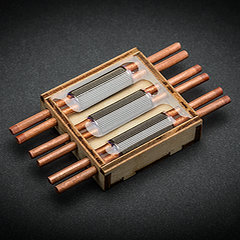
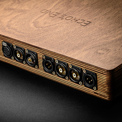
The Tunnelbridge is an elaborate, powered interconnect system. It features a stand-alone power supply unit that powers the Tunnelbridge interconnects for two purposes: first, to clone the incoming audio signal in real time, and second, to enable the two isolated circuits within the interconnects to create the conditions that allow distortion to arise only in relation to the cloned signal. This way the audio signal remains perfectly preserved, unaffected by distortion at all points through the entire cable length. The cloned signal, purposely created to be subjected to all distortion, is then intentionally discarded, never able to enter your gear.

Save ink and paper –
print from here!
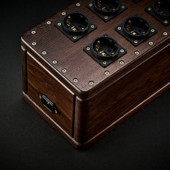
One Tunnelbridge PSU can be used for up to 8 mono channels (4 stereo pairs). One USB cable is required for each mono channel (therefore, 2 USB cables are required for each stereo pair of interconnects), regardless of whether these are of the RCA unbalanced or XLR balanced type.
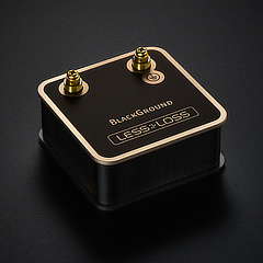
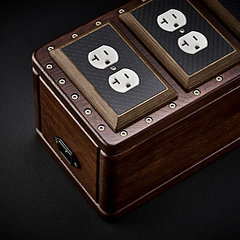
Power Supply Unit:
|
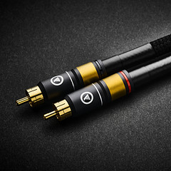
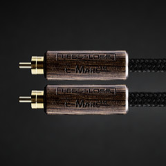
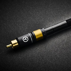
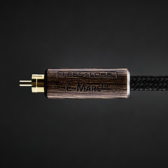
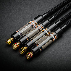
RCA Tunnelbridge cable (one stereo pair):
(legacy item - please inquire)
|
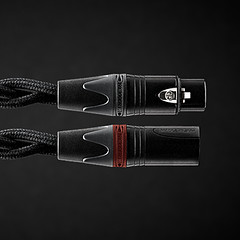
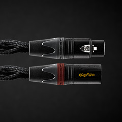
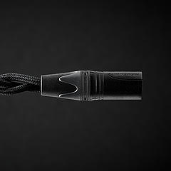
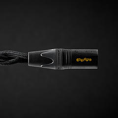
XLR Tunnelbridge cable (one stereo pair):
(legacy item - please inquire)
|
One pair of USB to USB mini cables: |

Free Worldwide express shipping.
Most deliver in 2-3 business days.
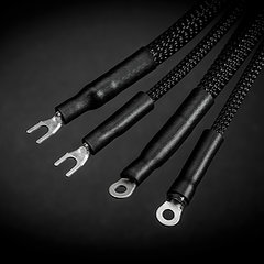
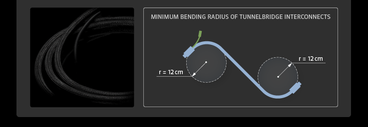
The Tunnelbridge interconnect cable itself contains a portion of the active electronic circuitry. Nevertheless, the cable remains flexible just as any standard cable. To ensure tension-free installation near the connectors, the Tunnelbridge interconnects are available in a minimum cable length of 1.5 meters.


Don’t let your audio signal "get scratched"
The moment an audio signal enters an interconnect, its distortion is inevitable. What the Tunnelbridge does with that distortion represents a leap forward in cable design—an area where many have come to expect progress in terms of inching forward with ever purer metals, better insulation, or more exotic twists and braids. To illustrate, consider the trust with which you reluctantly lend out your most prized LP. You know from experience that it’ll be returned irreversibly damaged, regardless of how careful the guy said he’d be with it. Once scratched, no matter how scrupulously you’d clean it, it could never again be the same. So it is with traditional cable models: distortion occurs as sure as that prized record will have been damaged, and the technology employed to remedy the situation is only good enough to produce an imitation, to try to distract our attention from the various imperfections of the audio signal.
What makes the Tunnelbridge brilliantly effective is that rather than allow the original signal to wind up in the hands of our "untrustworthy borrower," (sure to be returned damaged), instead it has a surrogate clone take the place of the original signal. In this way, the original signal remains perfectly preserved under watch, while only the cloned copy is "lent to the borrower."
This represents a stark contrast to traditional interconnect designs. Under these paradigms, audio signals are inevitably subjected to distortion while its designers make skillful attempts to make that deficiency inaudible. Think of the mixing and matching of materials. Just dealing with a single problem could involve testing different alloys, cable geometries, select insulator materials, and shielding solutions. Complicating the affair relentlessly further, each new element now in turn interacts with all others, making the task of high end interconnect design about as Sisyphean as it gets. Under such design paradigms, even if the effects of distortion are in various ways deemed satisfactorily masked, for that reason itself, the result will still sound different than had the signal never “been scratched” to begin with.
This is not to say that progress within this tradition is unachievable. After all, the Anchorwave falls into this category, and indeed offers very high performance. Nevertheless, the point remains: combating distortion by these means will always leave the sound different than recorded. Once change has occurred, there is no going back. Since interconnect design has been stuck in this paradigm, we’ve become accustomed to our attention being drawn away from inevitable signal losses with words like “speed” or “beautiful tone” (a means to steer a system’s overall timbre balance). These descriptions and their variants make no sense to describe the Tunnelbridge. The Tunnelbridge does not color the sound, it does not control the tone, and its affect on the audio signal is, quite simply, non existent; it is a true solution with lasting value, not another one of those “great sounding” cables (for some).


There are two main theories that describe how cables work, and so two theories that inform interconnect design. One describes a cable as a series of lumped parameters; the other as an evenly-distributed infinite series of capacitance (C) and inductance (L) values. C and L play the lead role in these two theories, and this is why many rely on C and L specifications to gauge high-end cable performance. Neither theory is complete, however, as each has its own problems. As you’ll see, breaking new ground in interconnect performance meant acknowledging these well-established theories while at the same time treading new ground to avoid the inevitable losses that traditional high performance interconnects are forced to try to balance.
Lumped Parameters
Under the theory of lumped parameters, an audio interconnect would have only negligible capacitance and inductance, because the output resistance of the audio signal transmitter is relatively low, and the input resistance of the signal receiver (a.k.a. the input) is relatively high. If we model an interconnect as a set of lumped parameters [1] (a low pass filter), the equivalent schematic of such a cable connected to the audio gear looks like this:
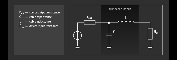
Because the cable’s resistance is so much smaller than the interconnected gear’s output and input resistances, with this model we can simply choose to discount this resistance of active loss, and add it to the gear’s resistance. Why? Because the electrical resistance of a cable is many orders of magnitude smaller than even the normal dispersion of 100k Ohm input resistors incurred during manufacturing. In the best of cases, these are manufactured to a +/- 1% tolerance of accuracy, and nobody can hear the minuscule influence of this small deviation.
In this model, the bandwidth of such a schematic, influenced by its capacitance C, is equal to f = 1/2πroutC, and influenced by its inductance L, is equal to f = Rin/2πL. Supposing a typical cable
capacitance value of C=100pF and rout =100 Ohm, then f, the bandwidth passed by the cable, is
about 15 MHz. Therefore, any typical cable, according to this model, should pass an audio signal
from component to component without any noticeable differences. But this obviously contradicts
our direct experience with audio interconnects—they don’t all sound the same.
A distributed series of capacitances and inductances
If we consider a cable as a series of distributed capacitances and inductances—which is what it actually is—because it has a length, a more accurate equivalent schematic now looks like this:
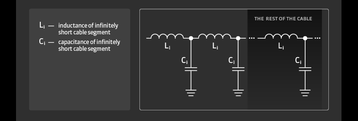
Here, L and C correspond to infinitely many inductance and capacitance values at infinitely small lengths of the cable [2]. The characteristic impedance of such a cable is defined as:

If we connect such a cable into a system whose source and receiver are both also of this equal impedance, we’d have a matched line [3], and theoretically we wouldn’t perceive distortion of frequency or impulse response. But this does not relate to the reality of real-world components: there is no official standard of matching impedances in home audio line signal applications. As a rule, the output impedance is made to be low, and the lower the better. The input impedance is made to be high, and usually, the higher the better. The aim of this is to create the best conditions for the first model we mentioned, as a set of lumped parameters.
Breaking free from traditional cable design
With the Tunnelbridge being a breakthrough in interconnect design, and C and L being such integral parameters in cable theory, you might wonder why we don’t list such seemingly crucial specifications of C and L to describe its performance. The truth is, the Tunnelbridge interconnects aren’t even based on C and L parameters. Why? Partly because of the inherent dilemma when basing an interconnect on such parameters: you can try to lower a cable’s L by keeping the wires close together, but not without raising its capacitance. Spreading the wires apart will compensate for this, but then the reverse occurs: C lowers and L rises—a catch 22. Regardless of how this game is played, both C and L are responsible for contributing conditions that cause distortion: microphonics (discussed in terms of microvibration, in the Anchorwave section) and the cable-insulation’s memory effect (discussed below). So, given the working relationship between C and L, and that they both create conditions that cause distortion, listing these values is not a good indicator of a cable’s performance. This is why a breakthrough in interconnect performance required abandoning traditional designs.

Crucial to interconnect performance is the memory effect of the insulation material that’s situated in the cable’s internal electric field [4]. This effect is often considered when investigating the influence of capacitors on sound quality. We can notice and even measure this effect by carrying out the following simple experiment. First, charge an electrolytic capacitor. Then, fully discharge it by shorting its two leads for a few seconds. Unshort the capacitor and then quickly measure its voltage. You’ll notice the voltage is at first 0, and then quickly begins to rise. The capacitor seems to "remember" that it was recently charged. Of course, a good capacitor should not exhibit such behavior.
Detailed studies show that this effect is not limited specifically to electrolytic capacitors. Any capacitor whose insulating material’s dielectric constant is substantially larger than 1, portrays this effect. As it turns out, the larger the dielectric constant (and therefore the larger the electric field inside the capacitor), the greater this memory effect. Because a cable is in this regard a capacitor (simply unrolled), the same holds for cables. When the signal is no longer present at the cable source, it can "show up" somewhere in the cable at a later time. It is no wonder, then, that manufacturers of traditional audio cables emphasize the importance of the quality of the chosen insulation material.

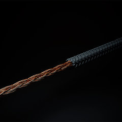
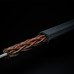
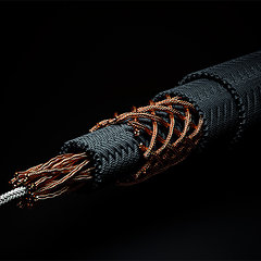
The main cross sectional structure of the Tunnelbridge is that of a coaxial design featuring two concentric shields. The original signal is fed into the center conductor; the outermost shield is the ground. By means of the Tunnelbridge integrated circuitry, located within the cable’s input connector, the middle shield receives a cloned copy of the original signal. The cloned signal’s function is to protect the original signal from loss and distortion arising from interaction between itself and the outer shield. In this way, the original signal in the Tunnelbridge doesn’t see any relationship to ground. Since the Tunnelbridge circuitry always maintains a zero voltage potential between the core conductor and the inner shield, there is no electric field there. If there is no field, there is no capacitance; nor is there any spontaneous dielectric polarization. Thus, at this location, we have tackled the “memory effect.” The protected signal in the core conductor, without having been exposed to the electric field, now makes its way through the cable into the input socket of your destination gear. The cloned signal, which collected all cable distortions through its interaction with ground, is entirely discarded by the Tunnelbridge circuitry before leaving the cable, and never contributes to any sound your speakers make.
After many experiments with electromagnetic field simulation software, real cable models, and many different audiophile systems, our final results surpassed our wildest expectations. Our theoretical model proved itself in practice. There was an obvious difference in sound quality when comparing the Tunnelbridge with traditional interconnect cables made with identical materials. When the cable’s insulation is not influenced by electromagnetic fields, its behavior is electromagnetically neutral. This means it is non-influential to the signal passing the core conductor, which never experiences capacitance or inductance in this design.


Isn’t a cable supposed to be completely passive? Won’t the cable’s active electronics affect the sound quality?
The cable’s electronics exhibit no direct influence because the signal which reaches the input of your gear never encounters the circuitry in the Tunnelbridge. There’s only one signal (the cloned signal) that encounters the Tunnelbridge’s circuitry, and that signal never enters your gear, but instead is entirely discarded by the Tunnelbridge. The only function of the circuitry is to eliminate the core signal’s capacitance and inductance which would normally corrupt the signal.
Let’s put some numbers on it. If, for example, the Tunnelbridge electronics were to cause a 0.01% distortion of the Bridge signal, then that fault would not result in a direct 0.01% distortion of the interconnect system’s final output; it would only cause a 0.01% rise in capacitance and inductance of the Tunnelbridge when compared to no internal fault whatsoever.
We respect your audio signal’s integrity the way the designer of your gear envisaged it. We assume from the outset that the signal introduced by your gear into the Tunnelbridge is ideal. Even though the Tunnelbridge is a powered audio interconnect, it doesn’t amplify, correct, influence, nor in any way beautify the signal it passes. The function of the electronics associated with the Tunnelbridge is merely to create ideal conditions for the signal to pass, completely unchanged, into the next piece of gear.
Footnotes and references for further reading
[1] Lumped parameters are a simplification in a mathematical model of a physical system where variables that are spatially distributed fields are represented as single scalars instead. For more see http://en.wikipedia.org/wiki/Lumped_parameters
[2] This pertains to the telegraph equations from the 1880s. For more see http://en.wikipedia.org/wiki/Telegrapher’s_equations
[3] For more on matched lines, see http://en.wikipedia.org/wiki/Transmission_line
[4] Ferroelectricity is a spontaneous electric polarization of a material that can be reversed by the application of an external electric field. For more, see: http://en.wikipedia.org/wiki/Ferroelectric