
 Beware of Fakes

 Pending Firewall module review and Analysis of Laminar Streamer vibration absorption characteristicsThursday 25 June, 2015
Dear customers,
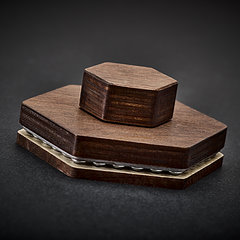
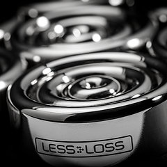
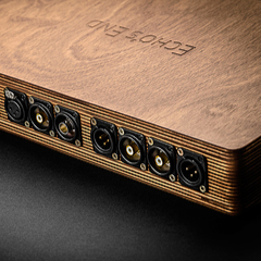
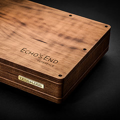
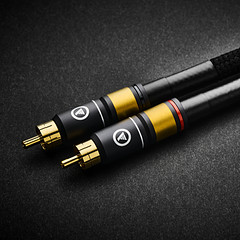
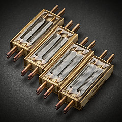
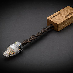
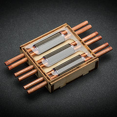
Firewall modules: pending Mono and Stereo review 8 Firewall modules with C13/C14 connectors attached have been delivered and received in good order by monoandstereo.com review webzine.  Watch this space (merely several published photographs... for now)! LessLoss Audio Firewall Modules Arrived I commented to Matej Isak on the quality of his photographs, upon which he replied "The best for the best ;)" When the review is completed and live, I will let you know. Laminar Streamer: Calibrated analysis of its resonance reduction In our earlier videos on the vibrational characteristics of the Laminar Streamer's chassis, some question may have remained unanswered as to how exactly the vibration absorption capability of a piece of audio equipment can have to do with its resulting output quality. We decided to show this to you using calibrated measurements. We want to show you how an equipment born vibration can enter the actual output signal cable of a connected interconnect cable. To do this, we devised a short cable of approximately 40 cm long, attached to which one end is this typical RCA connector: 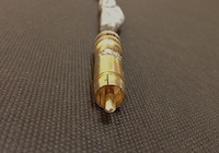 And on the other end is this small metallic flat plate to which we can tape a contact microphone: 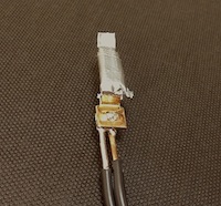 Here is a picture of the entire cable assembly: 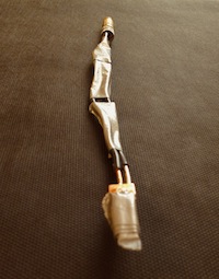 The contact microphone does not capture sounds which do not come off of the surface it is attached to. We used the AKG C 411 condenser contact microphone. It looks like this (the mic itself is the smaller element): 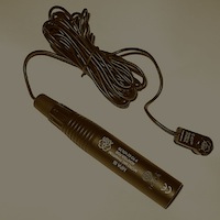 The AKG C 411 frequency response spectrum looks like this: 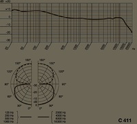 We used the True Systems Precision 8 professional microphone preamp and RME ADI-8 DS A/D converter to capture the data in digital form. The Laboratory 'Mice' Playing the role of 'laboratory mice' were three pieces of gear, namely: A very fine Nikko AM/FM Stereo Radio Receiver: 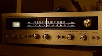 A professional TASCAM DA-88 eight track digital audio recorder: 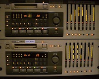 And the Laminar Streamer with an RCA socket installed: 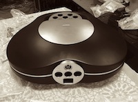 The Bouncing Ball Test This test consisted of the following rubber ball (pencil shown for size):  which was made to impact each of the pieces of gear in the following manner (but from 40 cm height each time):  At this point, I invite you to go here for interactive results showing pictures of procedures, audio of the collected data, as well as analysis using FFT software. Here is some of what you'll see there (you really need to hear the results, too): 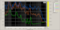 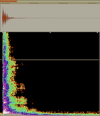 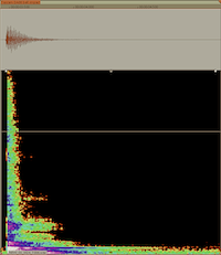 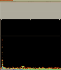 Why you need to see this When alternating currents travel along wires or circuit board traces, they create undulating magnetic forces amongst themselves, and these forces result in small vibrations which, through screws and soldering points, are induced into the structure of the equipment. In this test we have amplified the vibration so that our measuring equipment could give a good signal-to-noise ratio for easy and fool-proof comparison and analysis. As can be seen, this vibration goes through the RCA output and down the copper wire, where our output signal resides! This means that the vibration will also infest the next piece of equipment which is connected via the cable. Taking this aspect of design seriously is just part of what makes the Laminar Streamer so special. A lot of this type of works goes on behind the scenes here. So now that you know that you really need to see this, come on over and see it! Sincerely,
Louis Motek | LessLoss.com
 |
- Products
- Power Cables
-
 C-MARC™ Prime
The must have foundation for any sound system today.
From
$
486
C-MARC™ Prime
The must have foundation for any sound system today.
From
$
486
-
C-MARC™ Classic
The unique super-cable power cord everyone's talking about.
From
$
1148
-
 C-MARC™ Classic Entropic Process
The peerless, advanced Classic masterpiece.
From
$
1934
C-MARC™ Classic Entropic Process
The peerless, advanced Classic masterpiece.
From
$
1934
-
C-MARC™ Stellar Entropic Process
The crown jewel for highest performance power connection.
From
$
2450
-
- Loudspeaker Cables
- Interconnect Cables
-
 RCA C-MARC™
Cotton-clad true Litz • Whopping 2.3mm2 polarities
From
$
850
RCA C-MARC™
Cotton-clad true Litz • Whopping 2.3mm2 polarities
From
$
850
-
 RCA C-MARC™ Entropic Process
Our finest RCA cable • Polished Wenge barrels
From
$
1428
RCA C-MARC™ Entropic Process
Our finest RCA cable • Polished Wenge barrels
From
$
1428
-
 XLR C-MARC™
A hand-braided cotton-clad unique Litz construction
From
$
950
XLR C-MARC™
A hand-braided cotton-clad unique Litz construction
From
$
950
-
 XLR C-MARC™ Entropic Process
Stratospheric performance for the audio connoisseur
From
$
1615
XLR C-MARC™ Entropic Process
Stratospheric performance for the audio connoisseur
From
$
1615
-
- Digital Cables
-
 RCA Digital C-MARC™
Cotton-clad unique Litz design • Made only by LessLoss
From
$
510
RCA Digital C-MARC™
Cotton-clad unique Litz design • Made only by LessLoss
From
$
510
-
 RCA Digital C-MARC™ Entropic Process
Possibly the most subtle digital cable on the planet
From
$
858
RCA Digital C-MARC™ Entropic Process
Possibly the most subtle digital cable on the planet
From
$
858
-
 XLR Digital C-MARC™
Featuring a whopping 3 x 2.3mm2 Litz construction
From
$
570
XLR Digital C-MARC™
Featuring a whopping 3 x 2.3mm2 Litz construction
From
$
570
-
 XLR Digital C-MARC™ Entropic Process
Stratospheric performance for the audio connoisseur
From
$
969
XLR Digital C-MARC™ Entropic Process
Stratospheric performance for the audio connoisseur
From
$
969
-
- Grounding Cables
- Bulk Wire and Cable
- Signal Conditioners
-
 Firewall for Loudspeakers
C-MARC™ Plug-and-Play Speaker signal conditioning like you've never imagined From $ 1656 -
 Firewall for Loudspeakers
DIY version for Self-Installation For the Do-It-Yourself project enthusiast • Solder yourself From $ 800 -
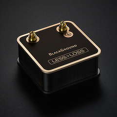 BlackGround DIY
Voltage-ground interface for a variety of applications
From
$
446
BlackGround DIY
Voltage-ground interface for a variety of applications
From
$
446
-
 BlackGround 8x/10x Speaker Base
Plug-and-play loudspeaker signal conditioner
From
$
3096
BlackGround 8x/10x Speaker Base
Plug-and-play loudspeaker signal conditioner
From
$
3096
-
- Power Conditioners
-
 Firewall 640x
Plug-and-play solution for any powered gear
Firewall 640x
Plug-and-play solution for any powered gear
C-MARC™ Entropic Process and standard lead versions From $ 654 -
 Firewall 640x DIY for Self-Installation
Self-solder and save!
From
$
320
Firewall 640x DIY for Self-Installation
Self-solder and save!
From
$
320
-
BlackGround DIY
Voltage-ground interface for a variety of applications
From
$
446
-
BlackGround 6x/10x Power Base
Plug-and-play power conditioner
From
$
2350
-
- Power Distributors
- Equipment Feet
- Field Conditioner
- DACs
- Power Cables
- Shopping Tools
-
Account
-
- Contact Us